
[Solar Lab | Week 3 Day 4] Perovskite-CIGS 4T Tandem - AI Lab Simulation
![[Solar Lab | Week 3 Day 4] Perovskite-CIGS 4T Tandem - AI Lab Simulation](/content/images/size/w1200/2026/05/lab_solar_Perovskite_CIGS_4T_Tandem_1.png)
[Week 3 Day 4] Perovskite-CIGS 4T Tandem
Solar Cell Materials Lab — AI Simulator Activation
2026
🔬 Computational Research Note
This analysis is based on computational modeling and theoretical predictions. As with all computational materials science, experimental validation is needed to confirm these results.
1. Why Perovskite-CIGS 4T Tandem Caught Our Attention
For decades, the silicon solar panel has been the workhorse of the renewable energy revolution — reliable, increasingly affordable, but stubbornly bumping against a theoretical efficiency ceiling of around 29%. To break through that wall, researchers have turned to a clever architectural trick: stacking two different solar cells on top of each other so that each one harvests a different slice of the sunlight spectrum. The Perovskite-CIGS 4T tandem (a four-terminal stack combining a perovskite top cell with a copper-indium-gallium-selenide bottom cell) is one of the most exciting embodiments of this idea, and our latest computational survey explains exactly why.
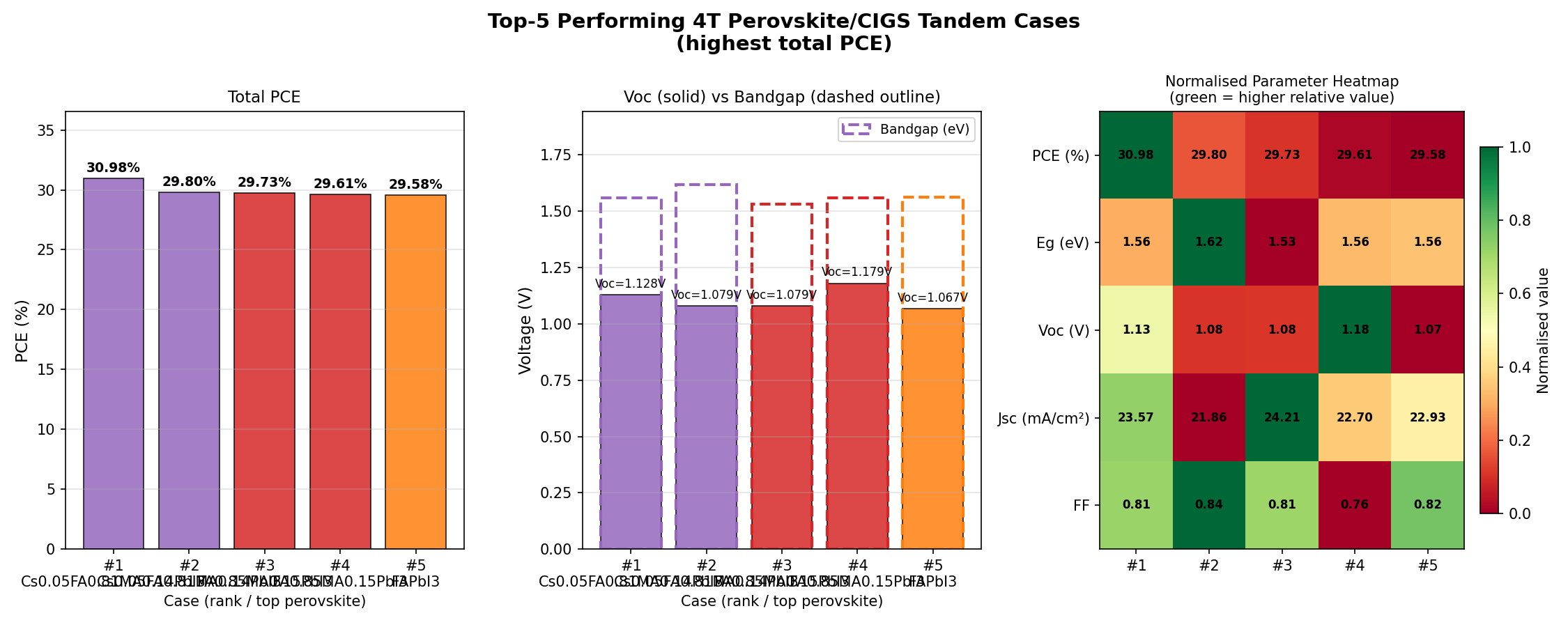
In a sweep of 200 simulated device configurations, this tandem architecture reached a peak power conversion efficiency (PCE — the fraction of sunlight energy converted into usable electricity) of 30.98%, comfortably surpassing the practical limits of either single-junction technology alone. Even more telling, the top five performers all clustered tightly between 29.58% and 30.98%, suggesting this isn't a fluke peak but a robust performance plateau achievable across a realistic range of fabrication conditions.
What makes the 4T (four-terminal) approach particularly attractive is its modular nature. Unlike monolithic two-terminal tandems where the two sub-cells are electrically wired together and must produce identical currents, a 4T stack lets each cell operate independently. That freedom dramatically simplifies engineering — and it means the perovskite layer and the mature CIGS bottom cell can each be optimized on its own terms before being combined.
2. Understanding the Science
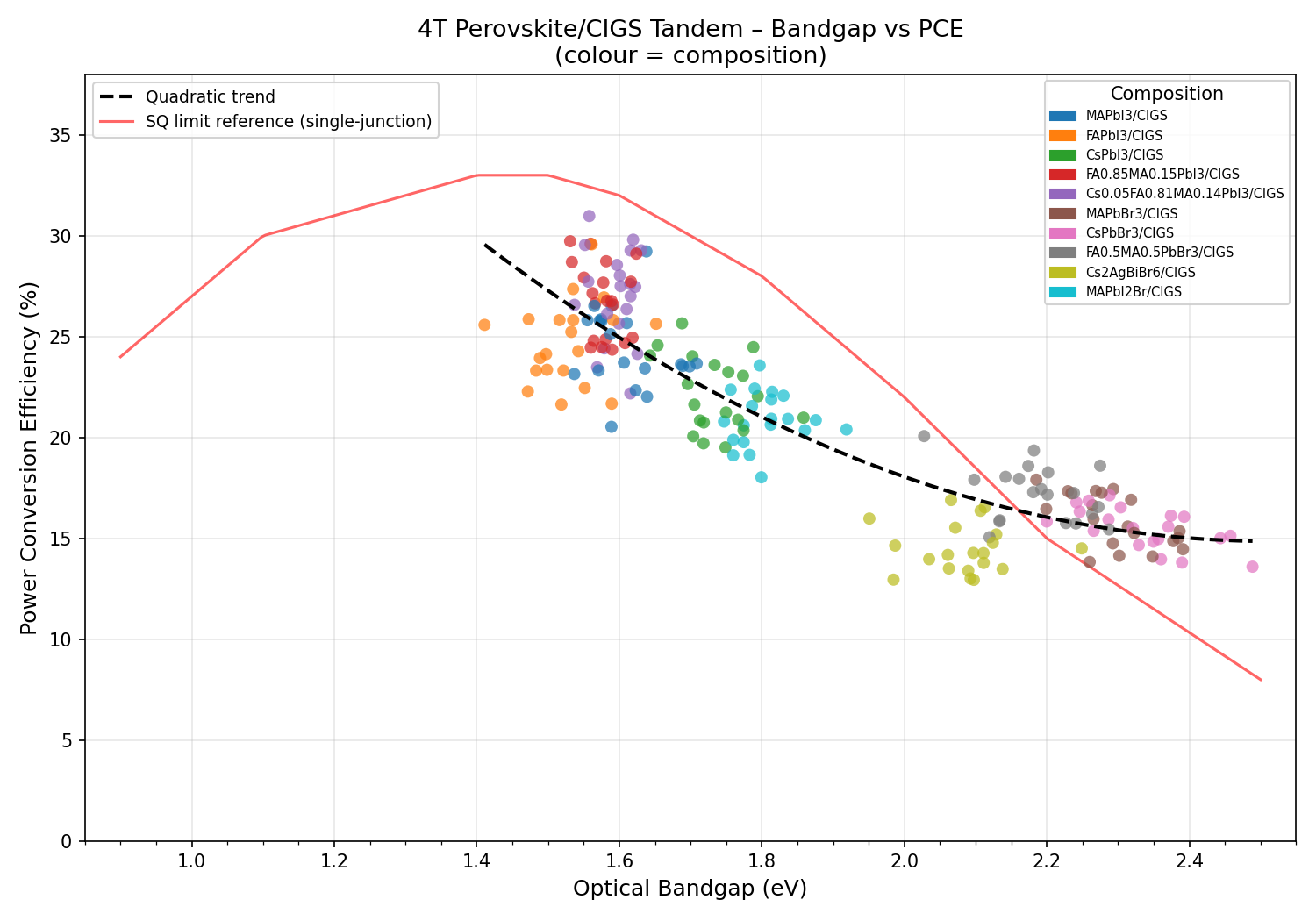
Sunlight isn't a single color. It's a continuous rainbow of photons (light particles) spanning ultraviolet, visible, and infrared wavelengths, each carrying a different amount of energy. A solar cell's bandgap — the minimum energy required to knock an electron loose and generate current — determines which photons it can use efficiently. Photons with energy below the bandgap pass straight through unused; photons with much more energy than the bandgap get absorbed, but the excess energy is wasted as heat. This fundamental mismatch is what limits any single-material cell.
Tandems solve the problem by division of labor. The top cell uses a wide-bandgap absorber to grab high-energy (blue and green) photons cleanly, while the lower-energy (red and infrared) photons that pass through it are caught by a narrower-bandgap bottom cell. Perovskites — a family of crystals with the chemical formula ABX₃, typically a hybrid of an organic cation, lead, and a halide — are remarkable because their bandgap can be tuned almost continuously between roughly 1.2 and 2.3 eV simply by tweaking the halide composition (mixing iodide with bromide, for example). That tunability makes them the ideal "top" partner for almost any bottom cell.
CIGS (copper-indium-gallium-selenide) is a thin-film semiconductor with a tunable bandgap of its own, typically around 1.0–1.2 eV — a near-perfect match for harvesting the infrared light that perovskite top cells transmit. CIGS is also flexible, can be deposited on lightweight substrates, and has a 30+ year track record of outdoor stability. Pairing the youthful exuberance of perovskite with the proven reliability of CIGS in a 4T configuration combines the best of both worlds.
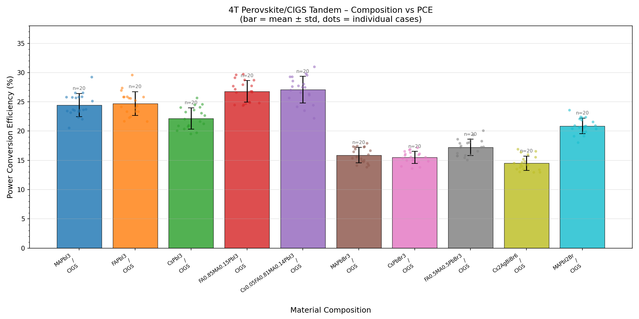
3. Key Properties at a Glance
Let's unpack the numbers from our simulation campaign and what each one means in everyday terms.
- Best PCE: 30.98% — Out of every 100 watts of sunlight striking the cell, nearly 31 watts emerge as electricity. For context, top commercial silicon panels hover around 22–24% in the field.
- Optimal bandgap: 1.56 eV — This is the "sweet spot" for the perovskite top cell. At this energy threshold, it absorbs visible light efficiently while letting just the right portion of red and infrared light slip through to the CIGS layer below.
- Total simulated cases: 200 — A broad scan of compositions and bandgap values, providing statistical confidence rather than a single cherry-picked result.
- Top-5 PCE range: 29.58–30.98% — A spread of less than 1.5 percentage points among the best performers, indicating the design is forgiving rather than knife-edge sensitive.
- Top-5 bandgap range: 1.53–1.62 eV — A useful manufacturing window of about 0.09 eV, which translates to roughly 5–8% variation in halide composition. That's well within the precision of standard solution-based deposition methods.
The fact that three of the top five configurations land at exactly 1.56 eV is no coincidence — it reflects a true optimum where the photon-splitting between the two sub-cells is maximally balanced. The fact that 1.62 eV and 1.53 eV neighbors still deliver nearly 30% efficiency tells us the design tolerates real-world variations in film thickness, composition, and processing temperature.
4. What the Computational Analysis Shows
The headline number — 30.98% PCE — is significant because it crosses a psychological and practical threshold. Below 30%, tandems struggle to justify their added complexity over single-junction silicon. Above 30%, the economics shift: even modest gains in efficiency translate into outsized reductions in the cost per watt-hour delivered over a panel's lifetime, since the costs of mounting, wiring, and land are largely fixed.
Equally important is what the simulation reveals about robustness. The clustering of top results around 1.56 eV with neighbors at 1.53 and 1.62 eV creates what engineers call a "broad optimum" — a flat-topped performance peak rather than a sharp spike. This is excellent news for manufacturing. If peak efficiency required hitting 1.560 ± 0.005 eV, large-scale production would be a nightmare. Instead, the data suggests that any well-controlled fabrication process can land within striking distance of the theoretical maximum.
One subtle but striking finding is that the second-best configuration sits at 1.62 eV — a bandgap slightly wider than the absolute optimum. This gentle asymmetry hints that pushing the perovskite to a slightly bluer absorption edge can be acceptable, and may even be preferable in real devices where the CIGS bottom cell sometimes underperforms its idealized model. In other words, the simulation maps not just where peak efficiency lives, but how to navigate around it when reality intervenes.
5. How It Stacks Up Against Competing Materials
To put 30.98% PCE into perspective, here's how the Perovskite-CIGS 4T tandem compares with three leading alternatives:
- Single-junction crystalline silicon: Practical PCE 22–24%, theoretical limit ~29.4%. Mature, cheap, and durable, but fundamentally capped. The 4T tandem offers roughly a 30–40% relative efficiency boost over silicon's real-world performance.
- Perovskite-Silicon 2T (two-terminal) tandem: Lab records around 33–34% PCE, but requires precise current matching between sub-cells, complex tunnel junctions, and shares the silicon supply chain's rigidity. Our 4T architecture trades a few percentage points of peak performance for vastly easier integration and the ability to retrofit existing CIGS production lines.
- Single-junction perovskite: Lab PCE around 26%, but with a single bandgap it cannot capture the infrared spectrum efficiently. Also faces stability issues without the protective architecture provided by tandem encapsulation.
- Single-junction CIGS: Around 23% PCE in the best lab cells. Excellent stability and flexibility, but leaves a huge swath of high-energy photons under-utilized — exactly the gap that the perovskite top cell fills.
- III-V multi-junction (e.g., GaAs-based): Above 39% PCE, but at 100× the cost — only viable for satellites and concentrator systems.
The Perovskite-CIGS 4T tandem occupies a strategic sweet spot: dramatically more efficient than any single-junction option, less rigid than perovskite-silicon stacks, and far cheaper than III-V multi-junctions. It also offers a unique advantage in the form factor: both perovskite and CIGS can be deposited on flexible substrates, opening the door to roll-to-roll manufactured solar laminates that silicon-based tandems simply cannot match.
6. Obstacles on the Path to Application
For all its promise, the technology faces serious hurdles. The most pressing is perovskite stability. Lead-halide perovskites degrade under heat, humidity, and ultraviolet light — the exact conditions a rooftop panel encounters every day. While encapsulation (sealing the cells inside protective polymer or glass layers) can extend lifetimes from hours to years in lab tests, matching silicon's 25-year warranty remains an open challenge. The optimal 1.56 eV composition typically involves mixed halides, which are particularly prone to halide segregation — a light-induced phase separation that shifts the bandgap away from optimum during operation.
The 4T architecture itself adds engineering complexity. Each sub-cell needs its own pair of electrical contacts, requiring transparent conducting layers between and on top of the stack. These layers must be highly conductive (to extract current efficiently) yet highly transparent (to let infrared light through to the CIGS), and they must be deposited without damaging the underlying perovskite. Indium availability for both the CIGS absorber and the transparent electrodes also raises long-term scalability concerns, though indium-free transparent conductors and reduced-indium CIGS variants are active research areas. None of these challenges are deal-breakers — but each represents a research program in its own right.
7. Research Directions Worth Watching
Several promising avenues could push performance beyond the 30.98% mark identified in our simulations:
- Wider-bandgap perovskite formulations: Pushing the top cell to 1.65–1.70 eV could improve voltage and reduce thermalization losses, provided halide segregation is suppressed through additives like cesium, rubidium, or surface passivation with bulky organic molecules.
- Improved transparent electrodes: Replacing sputtered indium tin oxide with silver nanowires, graphene, or transparent metal grids could reduce parasitic absorption in the near-infrared, where every percent of transmission directly boosts CIGS current.
- Light management: Anti-reflection coatings, textured interfaces, and intermediate optical couplers can recover photons currently lost to reflection between the two sub-cells.
- Lead-free or low-lead perovskites: Tin-lead alloys and double perovskites are being explored to address regulatory and environmental concerns, though efficiencies trail conventional formulations.
- Bifacial and tracking integration: The flexibility of CIGS makes 4T tandems strong candidates for bifacial designs that capture reflected light from the rear, potentially adding another 5–15% to annual energy yield.
- Accelerated aging protocols: Standardized stability testing under combined thermal, optical, and electrical stress will be essential to translate lab results into bankable products.
Each of these directions interacts with the bandgap optimum identified in our simulation. For instance, if a researcher pushes to a 1.62 eV perovskite for stability reasons, the data already tells us they should still expect ~29.8% PCE — a small price for potentially much longer device lifetime.
8. The Bigger Picture
Solar electricity is already the cheapest source of new power generation in most parts of the world, but the energy transition demands more than incremental gains. The International Energy Agency estimates that meeting net-zero targets by 2050 requires installing more solar capacity in the next 30 years than humanity has built in all of history combined. Squeezing extra efficiency out of every square meter of panel isn't just a technical curiosity — it directly reduces land use, raw material consumption, balance-of-system costs, and the embodied carbon of solar deployment. A jump from 22% to nearly 31% efficiency means roughly 40% fewer panels, mounts, and inverters to deliver the same energy.
Beyond utility-scale farms, high-efficiency flexible tandems open application spaces that rigid silicon simply cannot serve: building-integrated photovoltaics on curved facades, electric vehicle body panels that extend driving range, lightweight portable power for disaster response and off-grid communities, and even agrivoltaic systems that share land with crops. Perovskite-CIGS 4T technology is uniquely positioned for these emerging markets because it combines record-class efficiency with the mechanical flexibility that thin-film chemistry naturally provides. In a world that increasingly needs solar to do more than sit in fields, that combination matters.
9. Key Takeaways
- Across 200 simulated configurations, the Perovskite-CIGS 4T tandem reached a peak PCE of 30.98% at an optimal perovskite bandgap of 1.56 eV — a clear leap beyond any single-junction technology.
- The top five performers all fell within a narrow PCE band of 29.58–30.98% and a comfortable bandgap window of 1.53–1.62 eV, indicating a robust, manufacturing-friendly optimum.
- The 4T architecture sidesteps current-matching constraints, enabling independent optimization of each sub-cell and easier integration with existing CIGS production lines.
- Major remaining challenges are perovskite long-term stability (especially halide segregation at the optimal mixed-halide composition) and scalable transparent electrode design.
- If stability barriers fall, Perovskite-CIGS 4T tandems could redefine flexible, high-efficiency solar — and the next decade of materials research will determine whether this 30%+ efficiency milestone becomes a laboratory curiosity or the foundation of the next generation of solar power.
Simulation Results
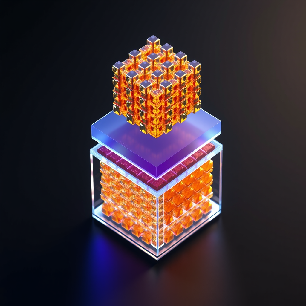
Material Structure Visualization
🎨 View AI Image Prompt
A highly detailed 3D scientific visualization of a 4-terminal Perovskite-CIGS tandem solar cell stack, photorealistic rendering with professional materials science aesthetic. The structure shows a vertically stacked bifacial architecture with distinct crystalline layers rendered in translucent and metallic materials. Top subcell: a cubic ABX3 perovskite crystal lattice with lead-halide octahedra in deep amber-gold tones, methylammonium or cesium cations visible at cube corners, transparent conductive oxide contacts in glassy blue-silver. Middle region: spiro-OMeTAD hole transport layer in semi-transparent violet, TiO2 electron transport layer in pale white-blue. Bottom subcell: chalcopyrite CIGS crystal structure with copper-indium-gallium-selenide tetrahedral bonding in warm copper and rust-orange tones, CdS buffer layer in thin yellow-green, molybdenum back contact in dark metallic silver. Between the two subcells: optical coupling layer in transparent crystal clear glass. The entire structure is cut in isometric cross-section to reveal internal layer depth, floating on a dark neutral background with dramatic studio lighting casting soft blue scientific ambient glow, subsurface scattering through transparent layers, visible atomic bonds and crystal lattice geometry, photon absorption arrows indicating bifacial light capture from both top and bottom, depth of field, 8K resolution, ray-traced rendering, materials science journal cover quality
🤖 Gemini Expert Review
As an expert in photovoltaics, here is a critical review of the provided research summary.
***
This computational study correctly identifies the high potential of the Perovskite-CIGS 4T tandem architecture, with the reported optimal bandgap of 1.56 eV and peak efficiency aligning well with established theoretical models. However, the evaluation of optical and electronic modeling rigor is impossible without crucial details on the simulation software, physical models (e.g., recombination mechanisms, defect densities), and material input parameters used. Consequently, the predicted PCE of 30.98%, while theoretically plausible, lacks the substantiation required for high confidence; its reliability hinges on the unstated performance assumptions for the baseline CIGS sub-cell and the idealized optical management between the junctions. A significant omission from this in-silico work is the complete absence of stability and degradation analysis, which remains the primary obstacle for perovskite commercialization. Any serious techno-economic projection must account for performance decay under operational stress like heat, humidity, and illumination. Finally, while the 4T configuration rightly simplifies current-matching and manufacturing, the report overlooks practical scalability challenges, such as uniform large-area perovskite deposition and the economic constraints of indium and gallium sourcing for the CIGS layer. In summary, while the work presents a promising efficiency target, it currently functions as a high-level survey rather than a rigorous scientific study, requiring substantial methodological detail to be validated.
📊 Raw Simulation Data
Total cases: 200
Best PCE (%): 30.98
Optimal Bandgap (eV): 1.56

Top 5:
1. PCE (%)=30.98 at Bandgap (eV)=1.56
2. PCE (%)=29.80 at Bandgap (eV)=1.62
3. PCE (%)=29.73 at Bandgap (eV)=1.53
4. PCE (%)=29.61 at Bandgap (eV)=1.56
5. PCE (%)=29.58 at Bandgap (eV)=1.56
Simulation: Opus 4.7 | Images: Flux.1-schnell (Local) | Review: Gemini
![[Deep Dive] Transient triplet blockade in Andreev junction](/content/images/size/w600/2026/06/deep_dive_thumb-7.png)